Concrete Cylinder/Cube Strength Ratio: In-depth Data
This article gives in-depth information on the Concrete Cylinder/Cube Strength Ratio. Concrete cube and cylinder specimens’ compressive strengths have a complex connection.
There are multiple factors that affect this relationship between the concrete cube and cylinder strengths.
The factors affecting the cylinder/cube strength ratio are:
- The method for Casting, curing and testing
- Geometry of specimen
- Characteristic strength
- Loading direction and machine properties
- Aggregate grading
Let us talk about each one of these
The method for casting, curing, and testing
The type of mould used to cast the cylinder specimens can have an impact on the cylinder/cube strength ratio. Cylinders can be cast in either rigid or non-rigid moulds, whereas cubes are always produced in rigid moulds (i.e., constructed of steel or cast iron).
The strength of cylinders made with cardboard moulds compared to those made in steel or cast iron has been shown to be somewhat lower (up to 3.5 percent).
The cylinder/cube strength ratio can be affected by the capping technique and out-of-plane surfaces. The cylinder/cube strength ratio is known to be impacted by the capping method in some way on cylinder strength.
Care must be taken to ensure that mold and specimen tolerances are met, or the cube strength and cylinder/cube strength ratio could be misleading.
If the specimen and mould tolerances are not respected, the cube strength and the cylinder/cube strength ratio may be misleading.
Two main factors are associated with the compression testing process:
- Type of mold
- Capping and surface planeness
Geometry of Specimen
Various aspects of specimen geometry are recognized to affect compressive strength test results such as:
- The specimen’s height-to-maximum lateral dimension (h/d)
- Lateral dimension (d)
- Overall specimen volume (V)
- Cross-sectional shape
h/d
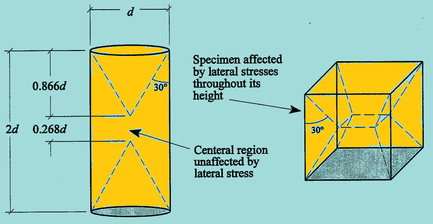
True uniaxial stress across a specimen is not possible, although being desirable. Lateral stresses in specimens are caused by friction between the machine platens and the specimen. As a result, there is a multiaxial condition of stress, which tends to make test specimens stronger.
Lateral stresses affect specimen stress state in a cone-shaped or pyramid-shaped region to a depth of about 0.866*depth at each end.
Such specimens as 150 x 300 mm cylinders with height (h)>=1.7*depth will have a region not usually experiencing these multiaxial stresses.
Multiaxial stresses influence cubes across the entire specimen. In the figure that follows, both cubes and cylinders are shown. For similar concretes, it can be anticipated that cubes will show stronger strengths than cylinders.
The following figure shows the general relationship between h/d and strength.
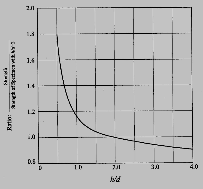
It is evident that the strength ratio is more sensitive to h/d for h/d < 1.5 than for h/d > 1.5. Cubes thus are more susceptible than cylinders to variations resulting from slight differences in h/d.
Lateral dimension (d)
Strength is inversely proportional to the square of lateral dimension (d2)
Since the lateral dimension of 150 x 300 mm cylinders and 150 mm cubes is the same, there is no problem when comparing these specimens. However, differences in size, like the 100 mm cube, have an impact on the cylinder/cube strength ratio.
Overall specimen volume (V)
Strength is impacted by specimen volume in two ways.
First, for specimens with a higher volume, the distribution of stress is comparatively more uniform. This is crucial because excessive stress concentrations might raise the likelihood of early failure and increase the variation of test results.
Cubes are more vulnerable to stress concentrations because a 150 x 300 mm cylinder has a volume that is around 1.65 times larger than that of a 150 mm cube.
The second effect of volume is that greater volumes are more likely to contain a weak unit that reduces strength. This second volume effect is closely related to the effect of d. Cross-sectional shape is not believed to have a significant effect on strength test results. Tests on cubes and cylinders with h/d = 1 yield similar results. A comparative study between 150 x 150 x 300 mm prisms and 150 x 300 mm cylinders showed little difference between strengths of the two specimen types. Thus, corrections based on shape are not needed.
Characteristic Compressive Strength
Nominal strength of concrete has been shown to affect the cylinder/cube strength ratio.
The compressive strength decreases as the ratio decreases.
Depending on the strength of the concrete, the cylinder/cube strength ratio ranges from 0.77 to 0.96. Every time the two geometries are compared, the relation between strength and the cylinder/cube strength ratio should be taken into account.
Direction of Loading and Machine Characteristics
Compression loads are applied in the direction of casting for cylinders, and perpendicular to the direction of casting for cubes. Because both cylinders and cubes are cast and consolidated in multiple layers, direction of loading is an important factor in the relationship between cylinder strength and cube strength.
See the difference in the below figure.
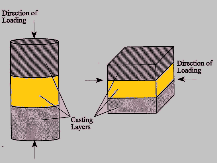
When cylinders are loaded, each casting layer occupies an entire cross-section, and receives the total load from the testing machine. Comparatively, each layer of a loaded cube, which stretches from top to bottom, bears some of the weight of the entire load.
The effect of flipping a cube can cause segregation, which is significant because it may result in differences in the elasticity and strength of the casting layers. These changes occur when cubes are turned over in every cross-section that is perpendicular to the direction of loading. The load is applied to each casting layer from a separate area of the platen. Use of non-segregating concrete should result in minimal variation in strength across a plane.
Aggregate Grading
It is well known that aggregate grading affects concrete strength in any construction or specimen. Due to the ratio of aggregate particle size to specimen dimensions, the effect is amplified for compression test specimens. For the ratio of d to maximum nominal aggregate size, the majority of standards establish a lower bound. This acceptable minimum usually ranges between 3 and 4.
Aggregate grading affects specimen strength through the “wall effect”, as shown in the next figure.
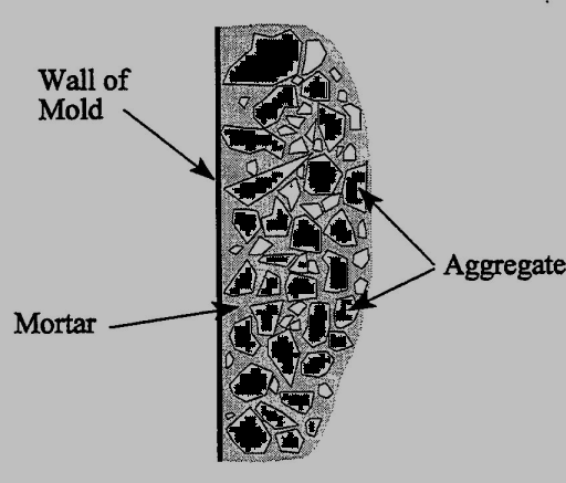
In concrete specimens a greater volume of space exists between the aggregate and mold wall than between aggregate particles within the specimen. The extra mortar at the walls increases the specimen’s compressive strength. Because this is a surface effect, compressive strength increase is greater for specimens with larger surface/volume ratios.
Comparing the surface/volume ratio for standard cylinders and cubes indicates how aggregate grading may affect the cylinder/cube strength ratio. The surface/volume ratio of 150 x 300 mm cylinders is 0.033/mm, but it is 0.040/mm for 150 mm cubes, suggesting that cubes are more sensitive to changes in aggregate grading than cylinders.
In fact, study revealed that 1) changes in aggregate grading had less of an impact on cylinder strength and 2) the cylinder/cube strength ratio declines as aggregate grading becomes more coarse.
Read Also: